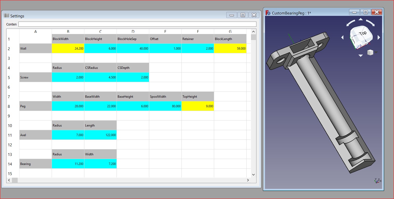
Bearing Peg 2.0 demonstrates an interactive FreeCAD model where changes made to the parameters are instantly reflected visually. The final product simply amazes me.
Following up my last my last post I was looking for something that would allow me to demonstrate. The BearingPeg came into focus because the design was complete and all I had was the .FCSstd file and thought I could just ‘parameter-ize’ it with a Settings spreadsheet.
The original BearingPeg design was a proof-of-concept effort that met my need without further development. I had thought about publishing a version with a shorter axle but didn’t have any actual need.
The Process
I created an empty ‘Settings’ spreadsheet and captured information from the parts in the V1.0 model like name, size, and position. I defined the objects in the spreadsheet and started creating them using the fx button to link the values to the Settings sheet.
Discovery
Setting the references to alias references requires a lot of pointing and clicking and it is difficult to keep track of where everything exists. So I switched to my standard approach and created a macro. Suddenly everything made sense and I was making amazing progress.
Iterative Process
Always use the macro to create the project. Changes to the Settings spreadsheet are reflected in the ‘genSettings’ function which creates the Settings spreadsheet if it doesn’t exist.
This means:
- You can delete all of the objects except the Settings sheet and recreate using the existing Settings
- OR
- You can close and recreate everything with the ‘initial’ settings.
Fine tune and debug within the Gui by drilling into the properties and making changes. When everything looks good reflect the changes into the macro and recreate the model to make sure they all were included properly.
Add a part within the Gui, reflect it’s creation within the macro and recreate the model. Or create parts in code and regenerate the project to reflect them in the Gui. At any point it should be possible to use the macro to rebuild the model from scratch.
Using the Gui you can see the commands it runs. These are the commands that need to be reflected in the macro. In a macro you can create a loop to create parts, set properties, label parts with useful names, and much more.
The process is a continuous back and forth where the model is destroyed and created from scratch again and again. This allows you to leverage the power of the Gui or Python, whichever makes the most sense for the task at hand, and in the end have ‘Source’ for the model.
Conclusion
Starting with the idea I could design in just the Gui, while true the conclusion is that it is far more efficient to write code. However, using the Gui and code makes light work of difficult tasks. In the end the completed project has two components:
- FreeCAD Model
- FreeCAD Macro -> (Does not need to be distributed)
Just the Model
The design is created so changes made to the Settings sheet are reflected immediately with just the FreeCAD (no macros) installed. The model contains the entire design which can be drilled into and changed for one-off modifications.
Source Code Protection
Using this approach I end up with a macro that captures _all_ the steps. Creating components in code is more efficient than using the Gui and drilling into all the properties and complex changes, like refactoring a name, are incredibly difficult. Having all the steps captured in code makes it possible to do complex modifications.
The ‘code’ (macro) used to create the design does not need to be part of the distribution. It’s purpose is to preserves the effort with the possibility of reuse and offers some protection for your IP.
Summary
The final product allows for all of the components to be changed from the Settings sheet and instantly reflected visually. This has exceeded my expectations.
